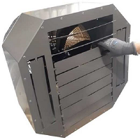
Destratifier description:
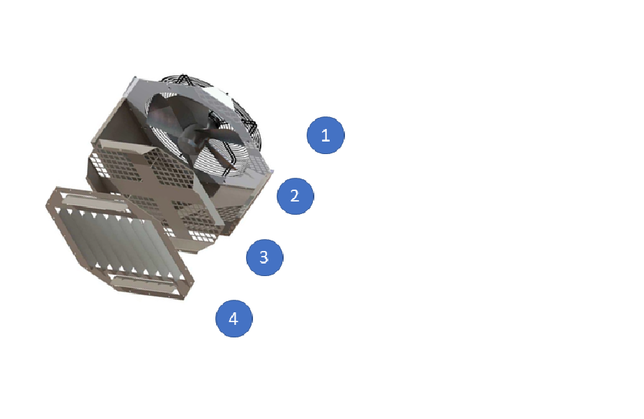
The device consists of the following parts:
- 1 - propeller protection grille,
- 2 - axial fan,
- 3 - diaphragm for APSAD compliance ("sprinkler" applications),
- 4 - diffuser with mixing turbulators.
Destratifier technical details:
| | H42 | H55 | H63 |
| Fan speed [ot/min] | 1 350 | 1 350 | 910 |
| Air flow [m3/h] | 3 960 | 6 050 | 10 300 |
| Recommended installation height [m] | 4 | 6 | 10 |
| Weight [kg] | 15 | 26 | 32 |
| Electrical input of the fan [W] | 150 | 420 | 550 |
| In [A] | 0,65 | 2,0 | 1,40 |
| Noise level [dB(А)] | 40 | 45 | 49 |
Destratifier sizes
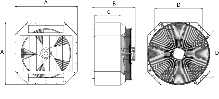
| mm | A | B | C | D |
| H42 | 585 | 247 | 405 | 448 |
| H55 | 585 | 247 | 415 | 448 |
| H63 | 725 | 247 | 415 | 538 |
Destratifier positions
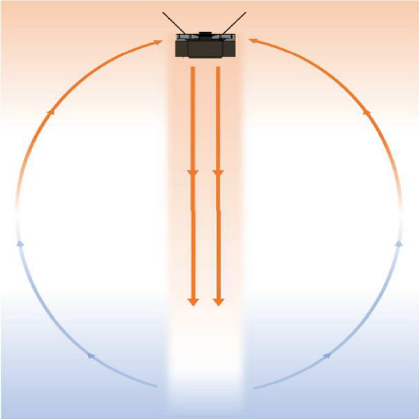
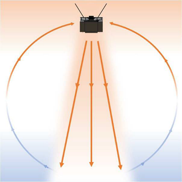
The layout depends on the geometric properties of the space and the number of designed destratifiers.
- devices are installed in the space onto the highest possible height,
- free space of at least 1 m on the sides and 0,5 m above the device is required for proper functioning,
- in spaces with a clear height of more than 8 meters, devices can be installed at lower levels,
- install devices at a height of at least 70% of the ceiling height so that air reaches the work zone,
- direct the slats of the device according to the requirements of the specific installation,
- install the devices on solid and permanent supporting structures
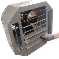
- Side turbulators of destratifier - air jet adjustment.
Side turbulators of destratifier - air jet adjustment
Blades perpendicular to the main air jet. The air jet can be concentrated for a maximum range or turbulent in order to reduce the air jet length (convergence of the side turbulators).
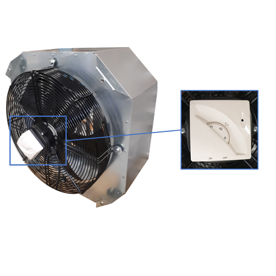
Destratification thermostat
Directly mounted and wired onto the motor in overhead airfl ow. Allows autonomous management of the regulation (on/off) of each device individually. A good setting of the destratifi cation temperature threshold can reduce heating energy costs by 50%. Reduction of energy consumption.

